=>Japanese
Return to "A. Home"
7.
18 MHz
Inv. delta loop
6.
18 MHz
Delta Zepp
5.
Ladder-line fed
HF GP
4.
Ladder-line fed
HF horizontal ANT
3.
14/18/21 MHz
Vertical ANT
2.
Old HF ANT remake
1.
Old HF ANT
Return to "A. Home"
7.
18 MHz
Inv. delta loop
6.
18 MHz
Delta Zepp
5.
Ladder-line fed
HF GP
4.
Ladder-line fed
HF horizontal ANT
3.
14/18/21 MHz
Vertical ANT
2.
Old HF ANT remake
1.
Old HF ANT
B1 HF antenna
5.Ladder-line-fed HF ground-plane antenna
The main antenna at the present (H31/2019) is a ladder-line-fed 14 MHz GP antenna. Being the resonant feeding, it can be utilized for other bands too.
This antenna was tried aiming at the following:
1. Low profile
2. Resilience to high wind
3. Low angle radiation
4. Multi-band operations
The items 1, 2 and 3 seemed to dictate a GP antenna and the item 4 a ladder-line.
However the ladder-line looked something exclusively for horizontal dipoles, and I have not heard of its application to GP antenna.
Yet I anyhhow tried the ladder line with 14 MHz GP antenna, because I have used for many years a ladder-line-fed 7 MHz horizontal dipole aiming at local contacts with a high radiaiton angle, and could not neglect the advantages of the resonance feeding.
As the combination proved to work remarkably well, I replaced the previously used antenna (18 MHz folding-element + AH-4) with this one.
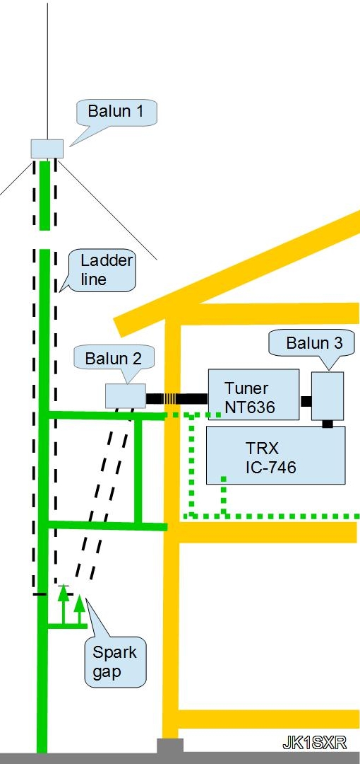
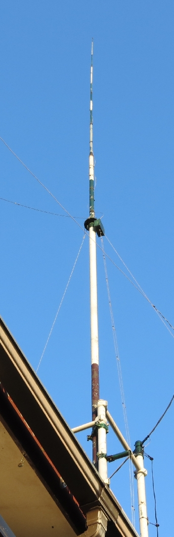
The overall configuration is as in the upper picture.
The feed point is at 10 meter above ground, and from there, a 5-meter vertical element upward, and three 5-meter radials 60-degree downward.
The ladder-line goes down from the feed point to the position 8 meters below, and then folds back upward to the 2nd floor where my shack is situated.
The spark-gaps are installed around the turnaroud point.
Through a balun the ladder-line is connected to a coaxial cable which enables an easy access to the indoor tuner through the wall
This coaxial cable undergoes considerably high SWR values depending on chosen bands. Thus shortest length and lowest loss possible are preferred. I use 2 meter long 10D-FB.
Below, some photos and explanations:
1) Ladder line
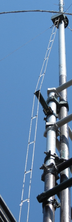
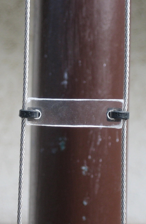 The element is stainless-steel stranded wire of 1.5 mm diameter.
The spacers are 1-cm high segments cut out from an acrylic-resin plate of 3 cm wide and 3 mm thick, wtih small holes at the edges.
1.5 mm wide cable-ties holds the elements and separators together at about 30 cm intervals to complete the lines.
As in the photo, this is a very simple structure, and the cable-tie lifetime was a worrisome point. However the same design has weathered for the last 4-5 years at my place.
2) Balun
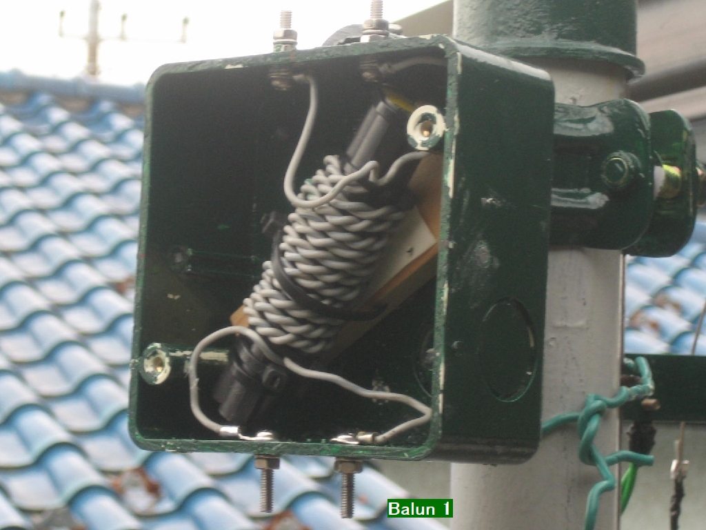
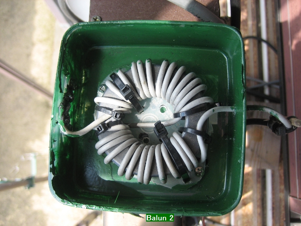
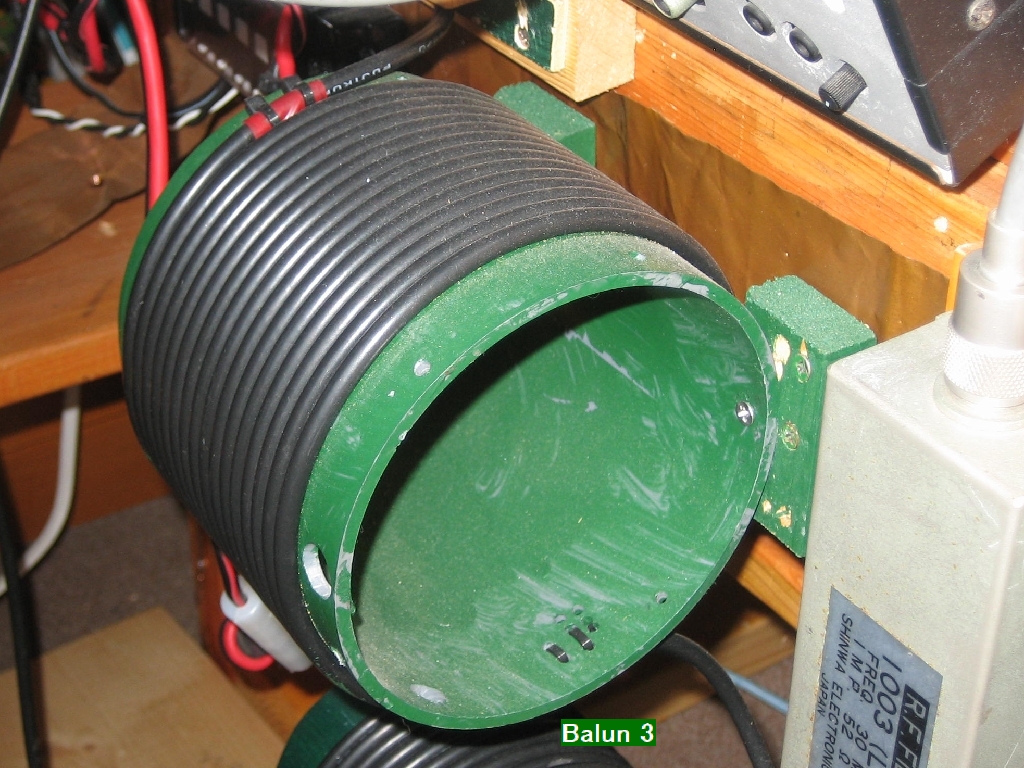 Totally three baluns are used.
At three locations, balun 1 in between the antenna element and radiators, balun 2 at the connection point of the ladder-line and the coaxial cable, and balun 3 placed between the antenna tuner and the tranceiver.
Probably the balun 2 only is OK. But I chose this way. No consistancy in the balun types is that I just used those happened to be at hand.
3) Spark gaps
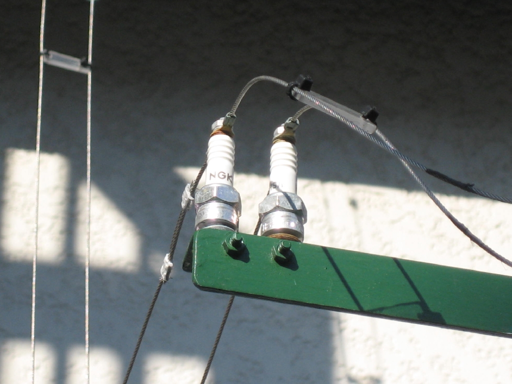 This was adopted to dissipate electrostatic charges.
The spark-plugs for small motor cycles are used.
This is intended for discharging the electrostatic charges accumulated on the antenna elements during the normal weather conditions, and not for countering the lightning hazards.
In rare occasions, even at a partially fine weather and when a thick and black cloud approached, the gaps discharge with the sound of piti, piti, -, -. This is noticeable at the shack too, as the speaker through PC audio amplifier gives off clicking sound in sync with the discharges, and can be used as an alarm.
Copyright © 2013 JK1SXR/abemasa. All Rights reserved.